
Five or ten years ago, a 60 kW rack was a lot of power. Today’s highest-density AI racks are already forcing a move beyond conventional 50/54 V distribution, and next-generation architectures are pushing toward 600 kW and, eventually, megawatt-class racks in the same footprint. Everything upstream of the GPU has to swallow that jump: the power supply, the bus bars, and the medium voltage gear.
Sam Abdel-Rahman is a system architect for server power supplies at Infineon, where he’s spent fifteen years tracking what AI is doing to the power supply unit (PSU) and feeding that back into the company’s device roadmap. We wanted his read on the question every power designer is now arguing about: when you convert grid power down to what a GPU actually eats, do you build with silicon, silicon carbide (SiC), or gallium nitride (GaN)? His answer is that there’s no universal winner, only a right place for each, and that the worst way to score them is on the price of the device alone.
That last point is the one engineers get wrong most often, he says. A SiC or GaN part can cost more than the silicon it replaces and still bring down the total system cost, because it lets you push more power through the same box. Look only at the price of the MOSFET and you can talk yourself out of the cheaper system.
The Data Center Engineer sat down with Abdel-Rahman to talk about the power chain from the grid down to the core, how the three semiconductor technologies split up the rack, the thermal and density tradeoffs that come with each, and why the pricier chip is so often the right call.
Watch the full interview
The following is our conversation, lightly edited for length and clarity.
How are data center power demands growing, and what is that doing to the rack?
Today we’ll focus on the rack, and specifically the AC-to-DC power supply.
Sam Abdel-Rahman: Let me start with a quick overview of how power flows through a data center. Utility power comes off the grid as high voltage, 13 to 35 kV. It enters the building and a medium voltage (MV) transformer steps it down to 480 V AC. Then you have the data center halls, the white space, where the racks and computing sit, and a busway distributes that 480 V AC to all the racks.
Each rack holds the power components: the PSU, the battery backup unit (BBU), and the server blades. On the server board there’s another stage, the intermediate bus converter (IBC), that steps the PSU output, say 50 V, down to 12 V and then down to the core voltage of the CPU or GPU. Today we’ll focus on the rack, and specifically the AC-to-DC power supply. The trends coming with AI are hitting the rack architecture, the PSU topologies, the power levels, and the voltages all at once. It runs both ways, too: the new architectures also push adoption of newer devices like SiC and GaN.
So AI is driving most of this?
Abdel-Rahman: To give you some perspective: three, four, five years ago we had traditional computing servers, with CPUs in the range of 200, 300, 400 watts each. A high-power rack five or ten years ago was maybe 60 kW. Today a single compute tray can carry four GPUs, and tray-level power has moved into the multi-kilowatt range. [Future Rubin Ultra-class designs are expected to push accelerator package power much higher again.]
Today’s rack-scale AI systems are already around 100 kW-plus, and the next generation is pushing toward 600 kW and eventually megawatt-class rack architectures.
It’s roughly twenty or thirty times the power. All that hungry AI silicon means everything upstream has to follow: the IBC, the PSU, the medium voltage infrastructure, the protection.
There’s one figure I keep coming back to. [According to the 2024 DOE/LBNL U.S. data center energy report, data centers consumed about 4.4% of U.S. electricity in 2023 and could reach 6.7% to 12% by 2028, depending on growth assumptions.] That’s significant growth.
Walk us through how the rack architecture itself is changing.
As the new GPU generation lands this year and next, racks need to reach 600 kW and beyond.
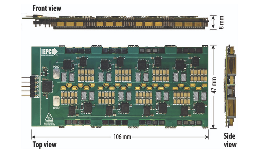
Abdel-Rahman: Take the current generation, call it gen one. The rack gets three-phase AC distribution, and it’s an integrated rack: the power supplies and the compute trays live together. The PSUs sit in a shelf, their outputs combine onto a busbar on the back of the rack at 50 V, and that 50 V feeds all the blades. That’s what we have today, and it’s limited to maybe 200 or 250 kW. The rack doesn’t have the space for more, and 50 V is itself a bottleneck, because as you push high power at 50 V the busbar current gets very high. The PSUs there are single-phase topologies, traditionally 3 to 5.5 kW, now 12 kW.
As the new GPU generation lands this year and next, racks need to reach 600 kW and beyond. The logical move is a sidecar, a side rack next to the IT rack that holds all the power components. It takes the AC, houses the PSUs and the BBUs, and cables its output over to a separate rack that’s all IT. With that separation you can get to 600 kW and 1.2 MW. But you can’t do megawatts over a 50 V distribution, so the PSU now delivers high voltage DC (HVDC), going from 50 V up to plus or minus 400 V, or 800 V. The current and the busbar losses drop accordingly. The PSU becomes three-phase in, HVDC out, which is a whole new set of topologies and a new set of devices.
Then there’s the last step, gen three: a local DC grid. Instead of the MV transformer stepping voltage down to distribute AC, you replace it with a solid-state transformer that takes the kV level straight down to 800 V and distributes a DC busway directly to the rack. At that point you don’t need a sidecar or a PSU on the side of the compute rack at all. That one is still in development, coming over the next few years.
When engineers weigh silicon, SiC, and GaN, what actually separates them?
SiC sits up in the high-power region at lower frequency. GaN sits in the bottom right, high switching frequency but limited in power.
Abdel-Rahman: Start with the device itself. On conduction, comparing silicon, GaN, and SiC, silicon carbide wins. There’s a curve of RDS(on) versus temperature: if the device sits at 25 °C, how far does its on-resistance climb at 100 or 125 °C? Ideally you want a flat curve, and SiC is very close to flat. That’s one of its big value propositions in high-power applications. You can run heavy loads and high loss without the on-resistance climbing at higher temperature.
On switching losses it flips. Take Qg, the gate charge, which includes Qgd, the gate-to-drain charge; that drives the turn-on and turn-off energy. GaN’s Qg is much lower than silicon or SiC, and the same goes for Qoss, the charge in the device’s output capacitance. So GaN can run at very high switching frequency without giving up efficiency. Silicon and SiC have a ceiling on switching frequency. GaN doesn’t.
There’s a well-known graph of output power on one axis against switching frequency on the other. SiC sits up in the high-power region at lower frequency. GaN sits in the bottom right, high switching frequency but limited in power. They each have a clear position, in servers, in solar, anywhere. There’s no single universal winner. Silicon is the mature, legacy technology, with a wide portfolio that fits a lot of topologies at lower frequency. SiC is very good for hard switching, for high voltages, especially above 1000 V, and for high-temperature operation. GaN does both hard and soft switching, but it shines at very high frequency and high density.
Does plain silicon still have a place?
Abdel-Rahman: It does, especially at lower frequency. In a single-phase totem-pole power factor correction (PFC) stage there’s a slow leg that doesn’t switch, and silicon is perfectly fine there on conduction loss and on cost. ORing devices are another spot. An ORing device sits at the output of each PSU when they run redundant or in parallel, to block reverse conduction, so it’s always on. Silicon is a perfect fit there.
How do the technologies compare when you’re optimizing for efficiency and power density at once?
You can push more power and pick up about a point of efficiency, holding the same heat dissipation while raising density.
Abdel-Rahman: In most cases you can’t increase density without increasing efficiency; they go together. Each unit, a PSU in a given case and volume, has a fixed thermal capacity. Push more power at the same efficiency and your losses go up, you dissipate more heat, and the temperature climbs. So to hold the temperature rise at an acceptable level, the designer has to raise efficiency as the density goes up.
Two examples show how the devices do both. Traditional PFC a few years back was silicon, a classic boost PFC at maybe 97 percent efficiency. SiC and GaN have a robust reverse-conduction body diode (GaN doesn’t have a body diode, but it conducts in reverse), and that enables the bridgeless totem-pole PFC. You can push more power and pick up about a point of efficiency, holding the same heat dissipation while raising density. It’s a design tradeoff: take the extra power, or take the same power at higher efficiency. Same story on the DC-DC side. Five years ago most LLC resonant converters ran at 100 kHz; today 300 to 400 kHz is typical, at equal or better efficiency. Put it together and PSU density has gone from 20 or 30 watts per cubic inch to approaching 150, using SiC and GaN in the right topologies. You couldn’t reach those levels with silicon.
How do those device choices ripple into thermal management?
Abdel-Rahman: It’s not a direct influence; it comes back to power dissipation. Take an 80 V-class GaN. In a 50 V output PSU you use 80 V devices, today mostly silicon, but the new 80 V GaN can go into the synchronous rectification FET, with much lower on-resistance in the same package than silicon. That relaxes the thermal and reduces the temperature rise. And it matters, because a 12 or 18 kW PSU is long, 600 to 700 mm, and the synchronous rectifiers sit almost at the far end of the fan, where the air is already heated up. Lower-resistance MV GaN cuts the heat dissipation right where it’s hardest to cool. There are several design practices like that, where the device choice lets you relax or improve the thermal solution.
How much does the system architecture dictate which device you can even use?
In the stacked or three-level case you only need 650 V devices, and now the door opens for all three technologies to compete on efficiency, density, and cost.
Abdel-Rahman: Often the topology and the voltage class decide for you. In a three-phase PSU the PFC is now typically a T-type, and its rectifying bridge is 1200 V silicon carbide. At 1200 V, SiC is the obvious choice; you can’t put silicon or GaN in that socket. By voltage class: above 1000 V it’s SiC; around 600 to 650 V is where all three compete; down at 80 or 40 V, SiC is out and it’s silicon versus GaN. Where you put the device, whether it’s the PFC rectifier or a synchronous rectifier, narrows the choice.
The architecture is also what accelerates adoption. The designer often has no choice but to take the voltage level and find the right technology. If you need an LLC with an 800 V input, 1200 V SiC is the obvious pick. But that’s where the designer can optimize. In that same example you could run an interleaved LLC with 1200 V SiC, or stack two LLCs, or use a three-level LLC. In the stacked or three-level case you only need 650 V devices, and now the door opens for all three technologies to compete on efficiency, density, and cost.
Here’s a good example of the architecture pulling in a device. The T-type three-phase PFC needs a 650 V bidirectional switch, two devices back-to-back to block in both directions. Today that’s two discrete silicon carbides placed back-to-back. Because GaN is a lateral device, you can monolithically integrate the two into one part, the GaN BDS, or bidirectional switch. Against two discrete devices it wins on density, component count, chip area, and capacitance. We may see it in the next generation of three-phase PSUs.
Are you seeing more real-world traction with any one of them?
Abdel-Rahman: There’s no clear winner, but go from grid to core and there’s a clear positioning, and at Infineon we build on every one of those stages. At the grid, the solid-state transformer, the gen-three step, runs high-voltage SiC above 2 kV; that will be dominant there. Downstream at the rack and the PSU, you need 1200 V and 650 V devices. SiC has a strong position because of the high-power trend and that low resistance-versus-temperature behavior. Silicon still dominates synchronous rectification today, but I expect medium voltage GaN to take more share as we go to 12 and 18 kW, because it cuts the number of synchronous rectifiers and the conduction and gate-drive losses. To give you a sense of scale, a 12 kW PSU might use a total of 96 devices in parallel across different groups. GaN shrinks that count.
Closer to the chip, the HVDC coming into the IT rack at 400 or 800 V hits a first stage called a hot swap, a circuit that controls inrush current when you plug a board into a charged bus. The hot-swap FET runs in linear mode, carrying current and blocking voltage at the same time, so you get a large current-times-voltage product, which is captured by the safe operating area, or SOA. Across silicon, SiC, and GaN, the winner there is the silicon carbide JFET, which has the highest SOA. After the hot swap you step that voltage down to 50, to 12, and to the 1 V core through IBC stages, which are low-profile, high-density, LLC-derived, and run up to megahertz. That’s a clear spot for GaN. So from grid to core you can watch it move from silicon carbide, to silicon carbide and GaN, to GaN.
If you had to name the biggest misconception engineers have about these three, what is it?
There are real production examples where a device, GaN or SiC, costs more on its own but lowers the total system cost when the system is designed well around it.
Abdel-Rahman: Cost. I always get asked how the three compare on cost for the same on-resistance, and that perception can become a barrier to even trying the technology. My recommendation is to understand what each device can do, see where it brings value, and analyze it in the system against your own specification. There are real production examples where a device, GaN or SiC, costs more on its own but lowers the total system cost when the system is designed well around it. In a PSU, the MOSFET is only part of the total cost. Raise that by 20 percent and the system cost might go up 4 or 5 percent. But if it lets me push 20 percent more power in the same form factor, the dollars per watt come out ahead. Don’t look at the device cost by itself.
The other misconception is dropping a wide-bandgap part into a system designed for silicon. Take an LLC at 100 kHz, pull the silicon, drop in GaN with the same dead time, same drive, same transformer, same frequency, and of course you’ll ask why you paid more for GaN. The right approach is to redesign: retune the dead time and the transformer, use GaN’s very low Qoss to get quick zero-voltage switching, shrink the magnetizing inductor, and fix the layout for a device switching above 50 V per nanosecond. What worked in silicon may not work there. The good news is that these were conversations we were having with customers a few years ago, and the market has matured to where SiC and GaN are becoming the default. We don’t have to educate as much anymore.