Philip Claussen of Poppe + Potthoff Maschinenbau explains why connectors, seals, and real-world pressure events matter as much as cold plates.
In direct-to-chip liquid cooling, the first weak link usually isn’t the cold plate. It’s the interfaces around it: connectors, fittings, threaded ports, and the sealing system.
That perspective came through clearly in our interview with Philip Claussen, managing director at Poppe + Potthoff Maschinenbau, a company that builds functional pressure test systems used to validate fluid-carrying components. As data center rack densities rise, Claussen argues that liquid cooling reliability is less about a single hero component and more about proving the whole assembly can survive real pressure transients, temperature swings, and service events—over and over again.
Watch the full interview
Automotive validation logic, adapted for the rack
Poppe + Potthoff’s core business is building “functional pressure test systems” for fluid-carrying parts: burst tests, leak tests, and pressure cycle/pulsation testing, often paired with temperature conditioning and real test media such as water-glycol. In data center liquid cooling, Claussen said his team applies the same validation logic used in industries like automotive and aerospace—because the failure consequences look different, but the physics doesn’t.
Hydraulically, data centers are just as unforgiving as automotive, as you need high confidence in leak tightness, near electronics.
“Automotive testing is shaped by more extreme environmental conditions,” he explained, and the industry is further along in standardizing test processes and profiles. Data centers are usually more controlled environments and less exposed to vibration, “but hydraulically, they’re just as unforgiving, as you need high confidence in leak tightness, near electronics.”
Claussen’s most actionable warning is about assumptions. In early designs, engineers often model a steady operating point and a relatively smooth pressure profile, with a handful of expected transient events. Real operation can be far messier.
“In design, engineers often assume a fairly smooth pressure … a steady operating point,” he said. “In real operation, you could face unexpected challenges—pump speed changes, different control effects, flow changes due to a part defaulting.”
And then there’s the phrase every mechanical engineer has heard but not everyone has experienced in an electronics-adjacent system: water hammer. Water hammer events when valves shut, plus interactions between parallel branches distributing flow, are “exactly what accelerate fatigue in connectors, hoses, threads, and seal interfaces,” explained Claussen.
From his perspective, a meaningful test profile needs to include both repeatable cycling (sinusoidal or trapezoidal pulsation profiles) and the “outside of the box events” that push parts into failure modes.
Why interfaces fail before cold plates
Asked which components fail in lifecycle simulations, Claussen said it’s often not the cold plate—because cold plates typically go through multiple design iterations before they’re fielded. The first weak link shows up elsewhere.
“The first weak link is often not the cold plate … but it’s mostly the interfaces, meaning connectors, fittings, threaded ports, and especially the sealing system,” he said.
That’s where assembly tolerances show up: side loads from hose routing, small misalignments, or even excessive torque during installation can change how a connector behaves once it’s in the rack.
Seals add their own complexity. Elastomers and seal geometries “don’t just sit there,” Claussen noted—they change with temperature. Thermal expansion mismatches between metal housings and polymer or elastomer seals can surface only after cycling.
Component tests aren’t enough: prove the full assembly
Component-level testing is necessary, he emphasized, but it’s not sufficient. “Many failures only appear when you test the full assembly,” Claussen said.
A liquid-cooled rack is full of connectors, hoses, cold plates, and clamps, all exposed to flow and pressure changes. Assemblies introduce real boundary conditions—bending moments, thermal gradients, and flow-induced forces—that “you simply don’t capture when you test one part in isolation.”
His recommendation: validate both the component and the assembled system, including chamber testing with pressure and temperature applied, to find weak spots before deployment.
What rising rack densities change
Looking ahead five years, Claussen expects higher power density to push designs toward higher total flow, higher allowable temperatures, and faster temperature ramp rates. Pumping power will grow with flow and pressure, increasing the pressure on suppliers to keep parts robust under cyclic pressures.
“More density results in more heat, and that heat needs to be dissipated,” he said. “Heat transfer into fluid is really vital,” which in turn drives optimization around flow, pressure, and heat transfer into the coolant.
One design rule for OEMs: treat the connection like the product
Claussen’s single design rule is blunt—and serviceability-driven: “Design the connection as if they’re the product.”
His reasoning is simple. “Every rack is going to be serviced at some point,” he said. That means connectors and seals have to stay leak-tight under pressure and survive repeated disconnect/reconnect cycles, handled by different people in real operational conditions. “To validate that entire assembly is really vital,” he added, because you’re designing the cooling feature as a system—not just the cold plate.
Interface standardization is starting to show up too—OCP’s Universal Quick Disconnect (UQD) effort is one example aimed at spill-free, interoperable couplings for liquid cooling.
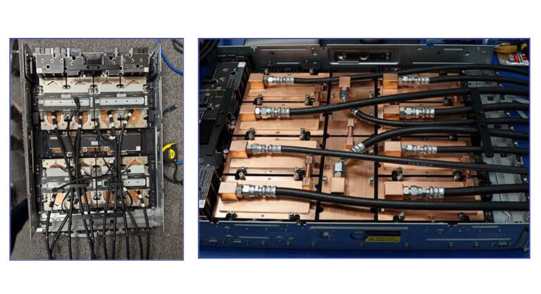
What “put to the test” can look like
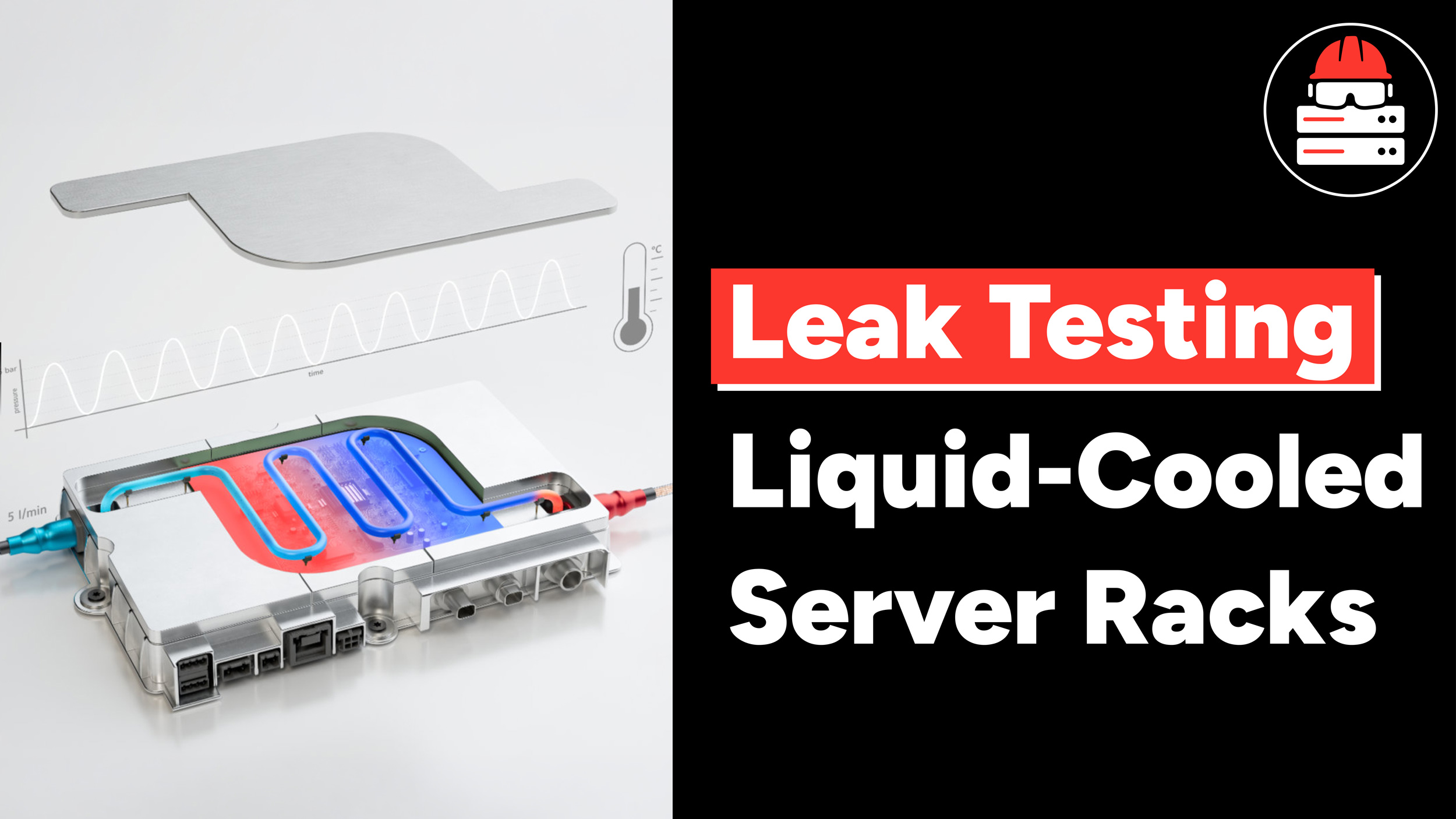
In a June 2024 Poppe + Potthoff write-up on validating liquid-cooled server components, the company describes test benches that can cover a wide range of mechanical and lifecycle conditions. Exact requirements vary by platform, but the example capabilities illustrate the direction of travel for qualification rigs in this space:
- Burst and leak testing up to 70 bar (about 1,100 psi).
- Dynamic pressure pulsation testing up to 20 bar (about 290 psi), with the option to incorporate water-hammer events.
- Sinusoidal and trapezoidal pulsation profiles up to 2 Hz to simulate service-life operating conditions.
- Testing with water-glycol emulsions or coolants such as PG25 in temperature-controlled chambers typically spanning -20°C to +90°C.
Those figures come from Poppe + Potthoff’s own materials and should be treated as example capabilities rather than universal prescriptions. But they reinforce the interview’s core takeaway: liquid cooling reliability lives at the interfaces and the pressure dynamics, so the validation program has to match the real hydraulics.